 ar
ar bg
bg hr
hr cs
cs da
da nl
nl fi
fi fr
fr de
de el
el hi
hi it
it ko
ko no
no pl
pl pt
pt ro
ro ru
ru es
es sv
sv tl
tl iw
iw id
id lv
lv lt
lt sr
sr sk
sk sl
sl uk
uk vi
vi et
et hu
hu th
th tr
tr fa
fa ms
ms hy
hy ka
ka ur
ur bn
bn mn
mn ta
ta kk
kk uz
uz ku
ku
load cell connection diagram
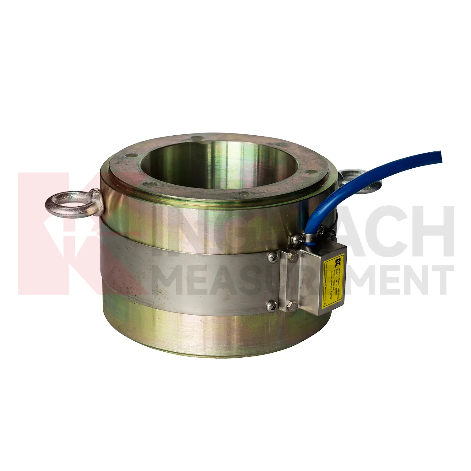
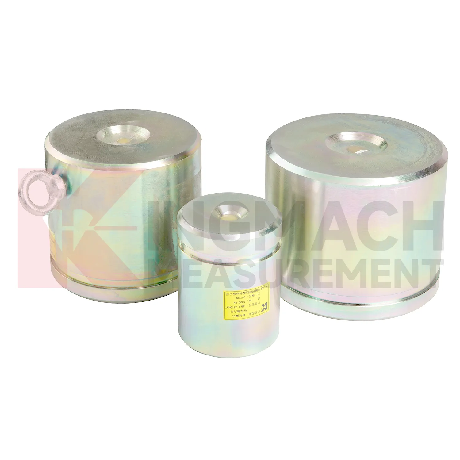
Kingmach load cell connection diagram products are built for projects that need force data with a clear technical trail. The hollow load cell JMZX-3XXXHAT uses an annular multi-string elastic steel structure and is listed from 500 kN to 8000 kN, with 0.1 kN sensitivity on the 500 kN model and 1 kN sensitivity on larger models. Its product file also lists a 50 year design life, digital output, automatic temperature correction, waterproof durability, and storage for 800 measurement records. Those details are relevant in bridge cable force monitoring, anchor testing, and long term structural health monitoring, where the same point may be checked for many years. Kingmach, based in Changsha, supplies sensors with readouts, data loggers, DTUs, and software platforms, so the measuring point can be connected to a wider monitoring network. For a project team, the important value is not a catalog claim. It is the ability to identify the sensor, read the same force channel consistently, compensate temperature influence, and keep a documented record when access becomes difficult after construction. For brand context, Kingmach Measurement & Monitoring Technology Co., Ltd. works from Changsha, Hunan, and its product pages group load sensing with structural health monitoring, engineering monitoring sensors, readouts, data loggers, instrumentation cables, and visualization software. That catalog context matters because a force sensor is often purchased with the equipment needed to read and archive it.
Application of load cell connection diagram
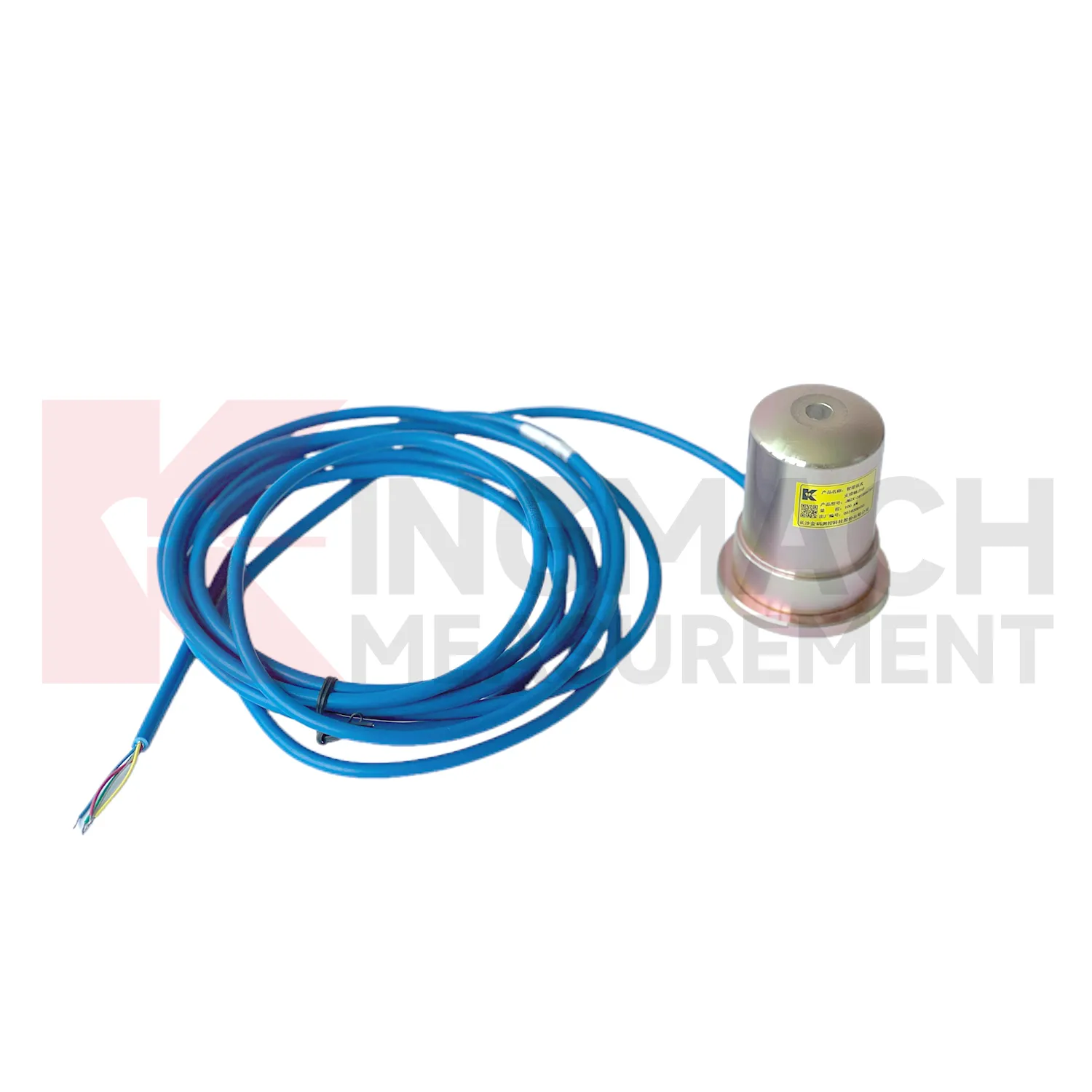
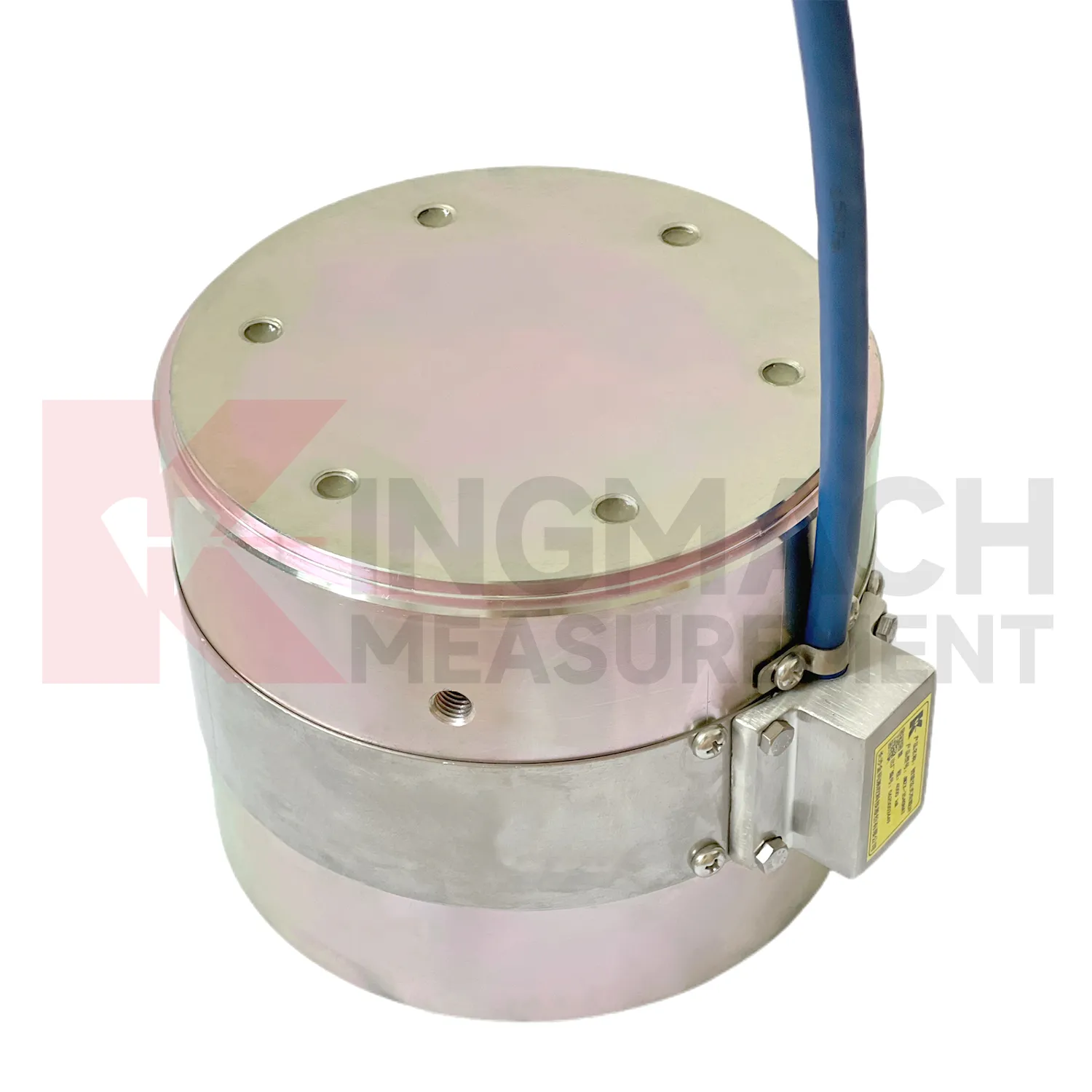
In monitoring networks that cover several structures, load cell connection diagram gives force and pressure points a place beside displacement, settlement, tilt, vibration, water level, and environmental data. The project pain point is interpretation across many channels. A force increase in a foundation pit may be normal after excavation, while a similar increase on a dam anchor after water level change may need closer review. Kingmach smart sensors can store model data, calibration coefficients, zero values, temperature data, and up to 800 records on relevant models. Load ranges across the family include 200 kN to 10000 kN for force products and 0.3 MPa to 8 MPa for earth pressure cells. When connected through readouts, data loggers, DTUs, or software platforms, these points can be reviewed by location and time. Good channel naming, consistent units, alarm thresholds based on design stages, and periodic field checks prevent the network from becoming a pile of disconnected numbers. Large networks also need a naming convention that crews can understand on site. A channel label that matches drawings, physical tags, and software screens prevents mistakes when alarms arrive during night work or bad weather. The platform should keep the raw reading history available, so later reviewers can see whether an alarm came from a real trend or a setup change.
The future of load cell connection diagram
As monitoring standards become more detailed, load cell connection diagram will be expected to support both engineering judgment and audit trails. Owners want to know whether a force change is real, when it began, how it compares with design stages, and what action followed. Kingmach load products already include technical features such as 0.5%FS precision on major force models, temperature correction, waterproof construction, direct kN display on axial force meters, and stored measurement records on smart designs. Future systems can tie these details to inspection workflows, maintenance orders, and asset management platforms. That means a load reading will not sit alone in a spreadsheet. It will connect to the sensor model, calibration certificate, installation photo, cable route, alarm history, and nearby movement data. Wireless links and AI screening may speed review, but the foundation remains disciplined measurement. The future belongs to force monitoring records that can be checked, repeated, and understood years after installation.
Care & Maintenance of load cell connection diagram
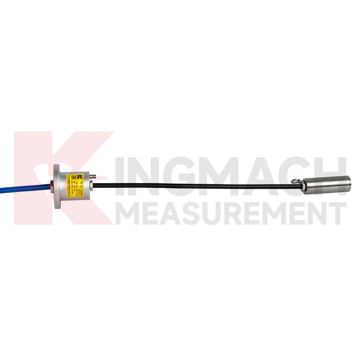
For load cell connection diagram used in bridge cable or anchor monitoring, maintenance should focus on the load path and the environment around the sensor. Hollow load cells list 500 kN to 8000 kN ranges, temperature correction, waterproof durability, and 800 stored measurement records on smart models. These features support long term observation, but they do not replace site checks. During installation, make sure the washer, bearing plate, anchor head, and sensor axis are properly seated. Record the first stable force after locking and keep the temperature reading with it. During operation, inspect cable protection, connector sealing, corrosion exposure, and any change near the anchor zone. Compare force records after seasonal temperature shifts, heavy traffic periods, maintenance work, or extreme weather. If one point changes while nearby points remain stable, check the bearing surface and wiring before treating the reading as structural behavior. A clean maintenance log helps separate sensor issues from real force redistribution.
Kingmachload cell connection diagram
load cell connection diagram supports decisions that are too important to leave to visual inspection alone. A bridge anchor plate may look unchanged while force redistributes between strands. A deep excavation support may still be straight while axial load rises. A pile test may appear steady while the loading system introduces eccentric force. Kingmach's load monitoring range gives engineers several instrument formats for these different questions, including hollow, solid, axial force, and pressure related products. The field value depends on repeatability. A reading taken today must be comparable with the first stable reading, the next load stage, and the record after temperature changes. That is why calibration coefficients, zero values, cable labels, installation photos, and compatible readouts matter. When all of those details are controlled, force monitoring becomes a practical inspection record rather than a one-time test result. That discipline turns a single load point into evidence that can be reviewed months later.
FAQ
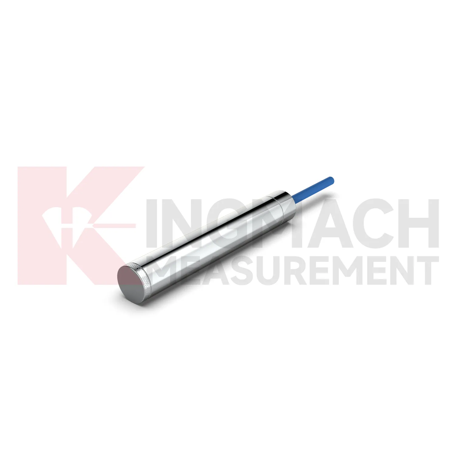
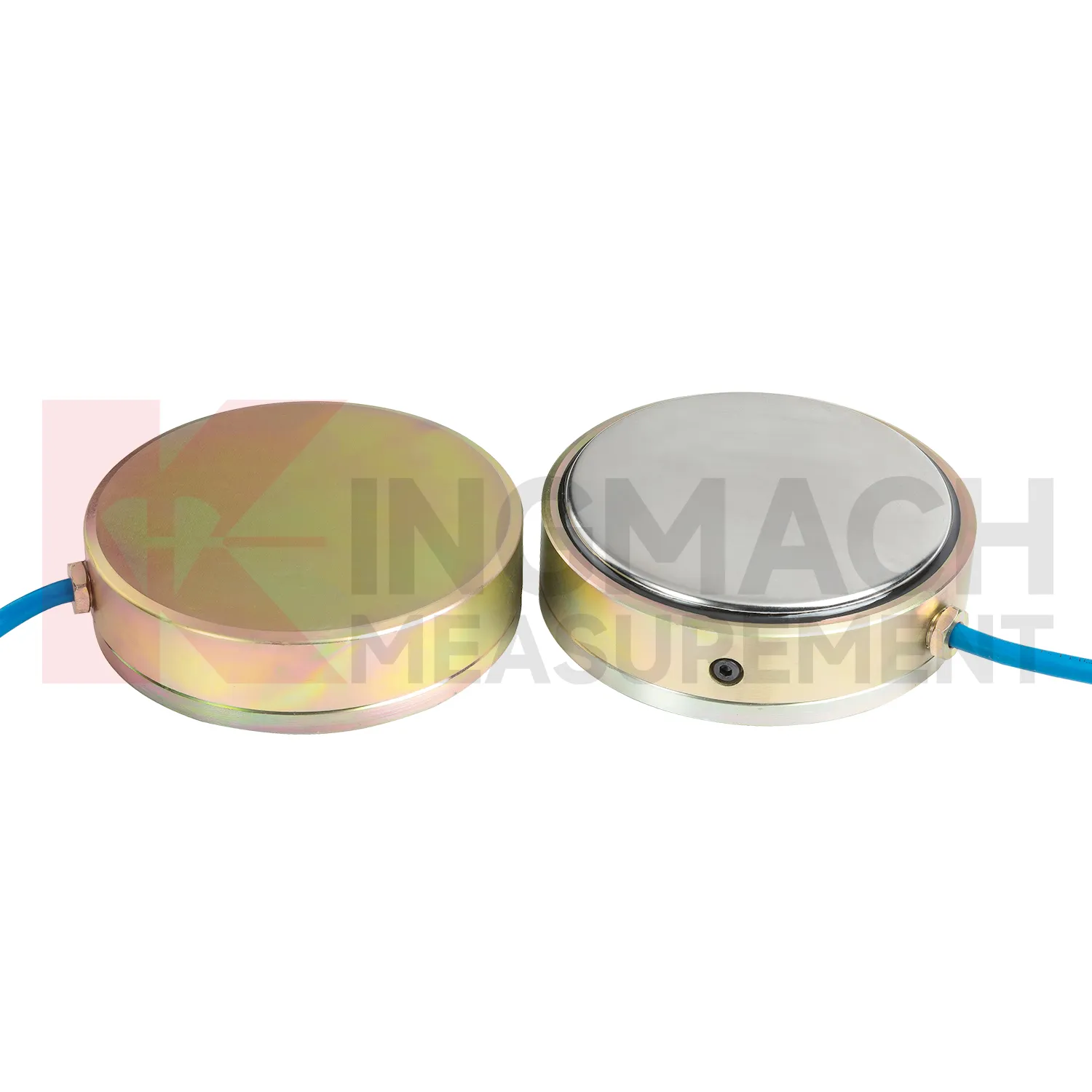
Q: When is a solid load cell connection diagram more suitable than a hollow type? A: Solid models are commonly used for compression load, pile load testing, bridge pier support checks, and heavy bearing capacity measurement. Q: What specifications does the Kingmach solid load cell list? A: The JMZX-35XXHAT line lists 1000 kN to 10000 kN ranges, 0.1 kN resolution, 0.5%FS precision, and -30°C to 80°C working temperature. Q: How much overload margin is listed? A: Product information lists 20 to 50%F.S. range overload and 300 to 400%F.S. failure overload. Q: What installation errors affect accuracy? A: Eccentric loading, uneven bearing plates, side load, cable pulling, and missing zero records can all distort results. Q: What records should be kept for acceptance? A: Keep calibration coefficient, model, serial identity, load stages, temperature, zero value, and readout setting.
Reviews
Ryan Lewis
Fast delivery and excellent product quality. The accelerometers and tiltmeters are highly reliable. Strongly recommend this company.
Joshua Clark
We ordered a full monitoring solution including sensors and data loggers. Everything works seamlessly together. Great supplier!
Latest Inquiries
To protect the privacy of our buyers, only public service email domains like Gmail, Yahoo, and MSN will be displayed. Additionally, only a limited portion of the inquiry content will be shown.
Emma***@gmail.comCanada
Dear Sir/Madam, we are interested in displacement transducers and settlement sensors for a geotechni...
Mia***@gmail.comNetherlands
Dear team, we are interested in your readouts & data loggers compatible with multiple sensors. Do yo...