 ar
ar bg
bg hr
hr cs
cs da
da nl
nl fi
fi fr
fr de
de el
el hi
hi it
it ko
ko no
no pl
pl pt
pt ro
ro ru
ru es
es sv
sv tl
tl iw
iw id
id lv
lv lt
lt sr
sr sk
sk sl
sl uk
uk vi
vi et
et hu
hu th
th tr
tr fa
fa ms
ms hy
hy ka
ka ur
ur bn
bn mn
mn ta
ta kk
kk uz
uz ku
ku
load cell wiring diagram
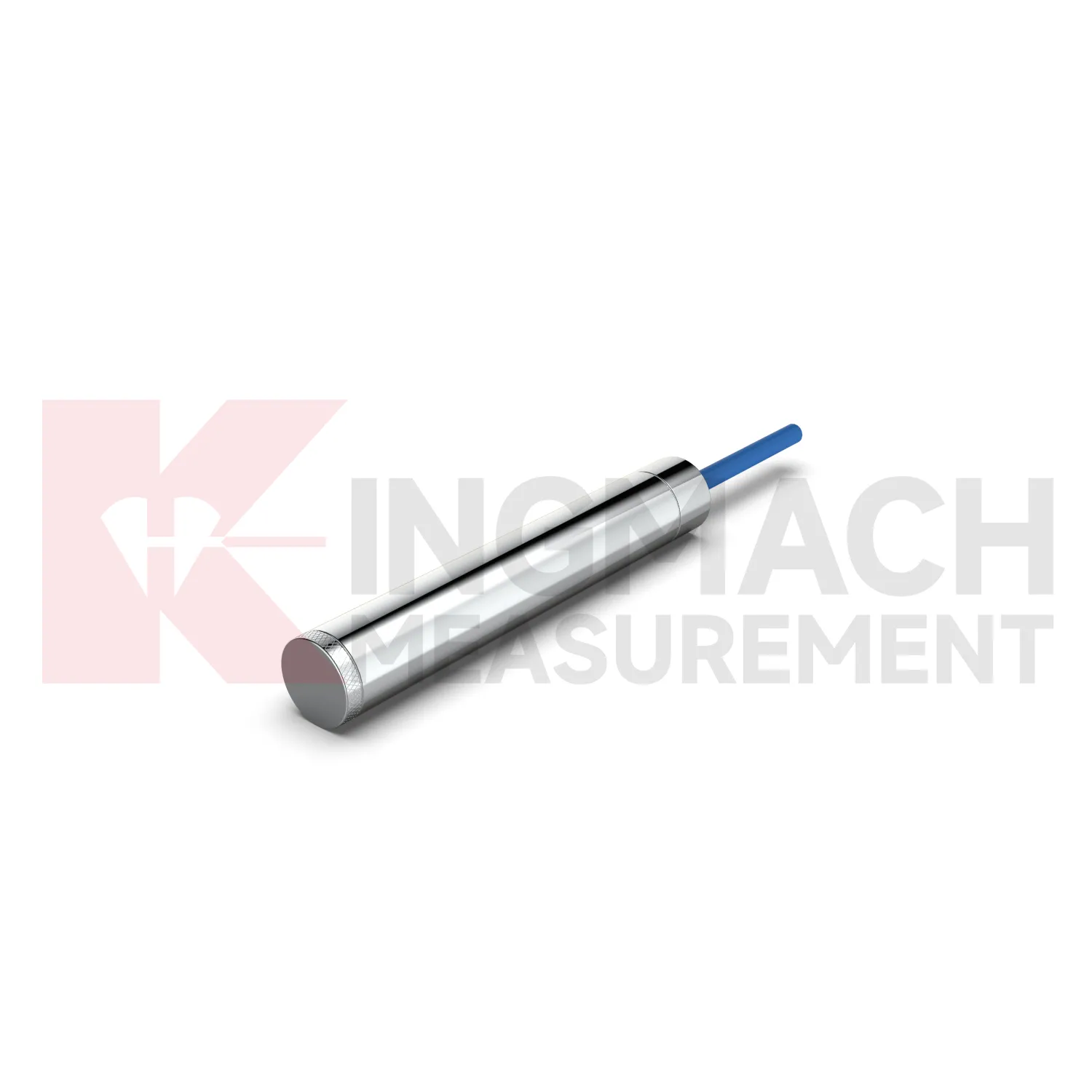
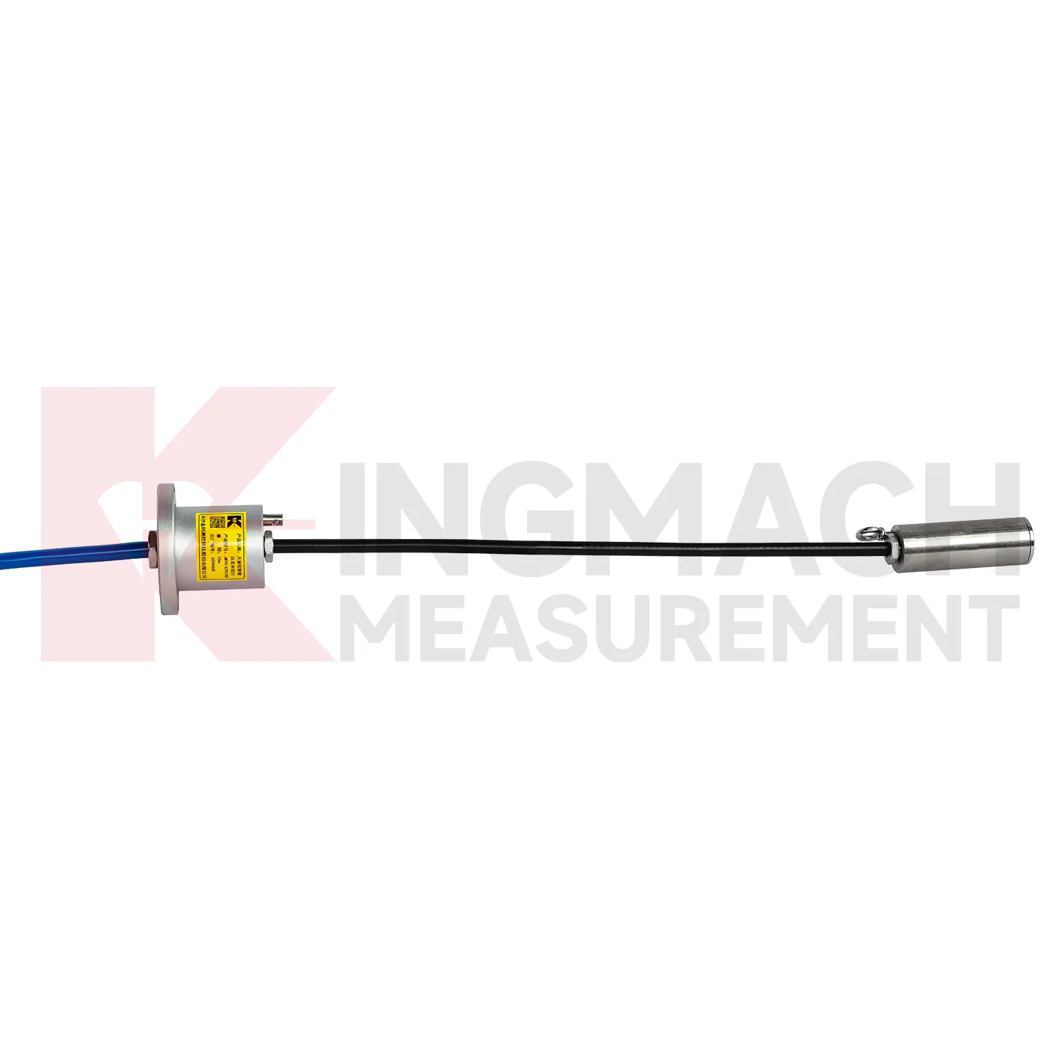
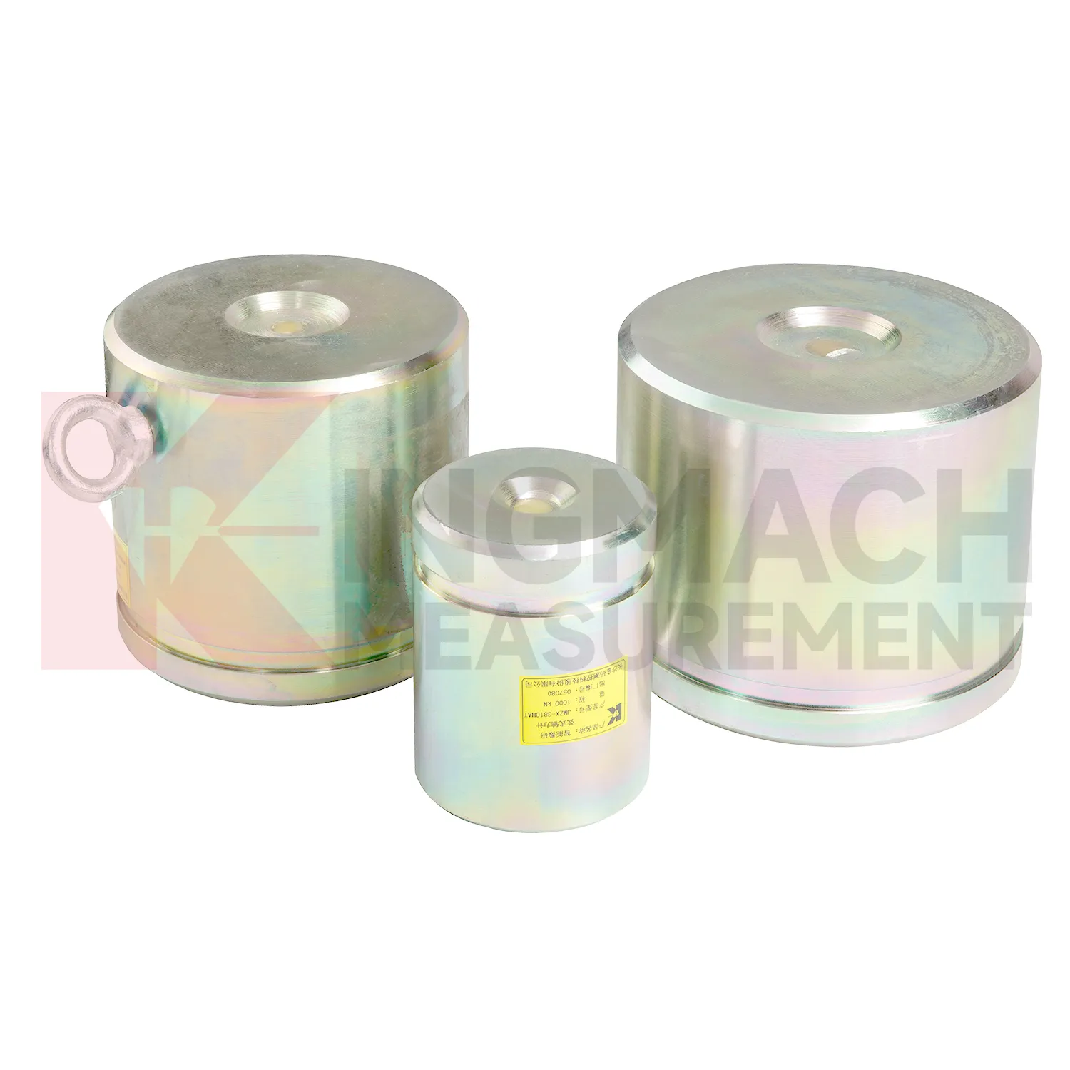
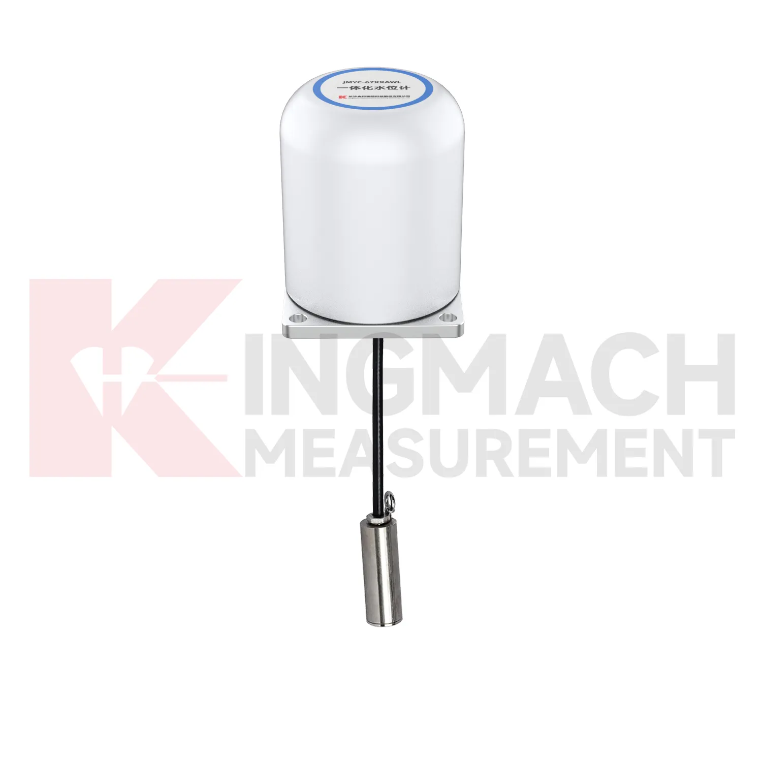
Kingmach load cell wiring diagram can also include pressure related sensing where soil or structural contact pressure is the main concern. The JMZX-50XXAT/ATM earth pressure cell family is listed in 0.3 MPa, 0.6 MPa, 1 MPa, 2 MPa, 4 MPa, 6 MPa, and 8 MPa ranges, with 0.001 MPa pressure resolution, 0.5%FS pressure accuracy, and ±0.5°C temperature accuracy. The product information also refers to high strength elastic steel, waterproof and durable construction, a 50 year design life, 800 stored measurement sets, and automated acquisition support. For retaining structures, embankments, dams, tunnels, and foundation pits, those pressure records help engineers understand whether earth load, water influence, compaction, or excavation stage changes are affecting the structure. Kingmach's broader monitoring catalog allows these readings to be compared with settlement, water pressure, displacement, and tilt. That connection is important because pressure change without movement may still indicate a developing load redistribution that deserves closer inspection. The same site places these instruments within a wider monitoring range, including piezometers, water level meters, displacement transducers, settlement sensors, tiltmeters, cables, data loggers, and software. That wider range helps when a project needs force data to be compared with movement, water, and temperature records.
Application of load cell wiring diagram
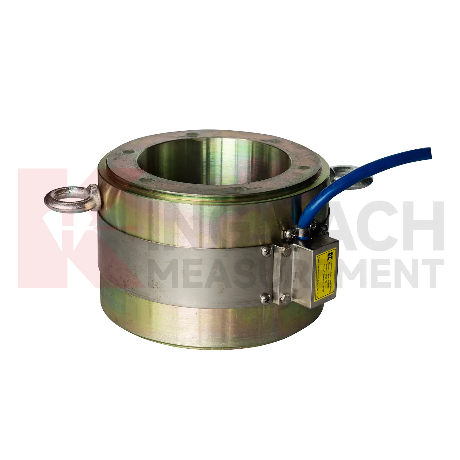
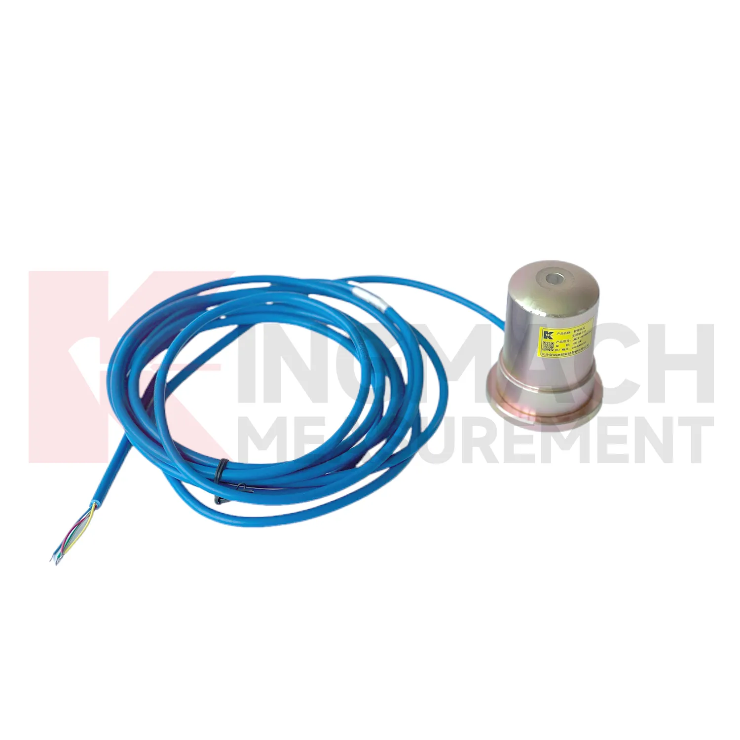
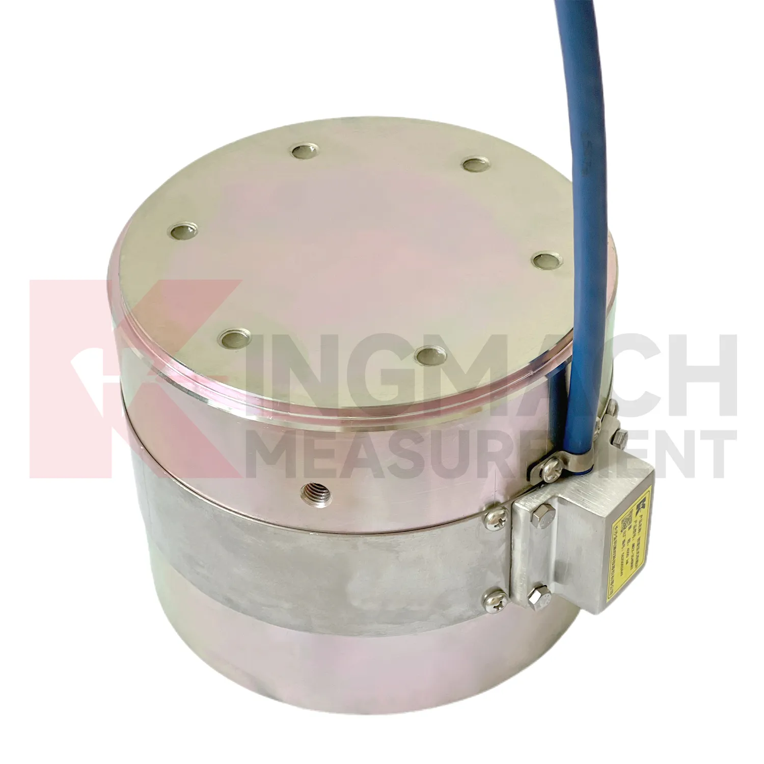
In dam and hydropower monitoring, load cell wiring diagram can be used for anchor force, concrete bearing pressure, gate structure load checks, earth pressure near embankments, and long term load review around seepage control areas. The monitoring difficulty is durability. Access may be limited, water influence is persistent, and seasonal temperature changes can mask small force trends. Kingmach hollow load cells list a 50 year design life, waterproof durability, automatic temperature correction, digital output, and 800 stored measurement records. Earth pressure cells also list a 50 year design life, 0.5%FS pressure accuracy, and ±0.5°C temperature accuracy. These parameters support long observation periods, especially when readings are tied to reservoir level, seepage, rainfall, and temperature records. For dam owners, a single force value is rarely enough. The trend should show whether anchors remain stable, whether pressure increases after impoundment, and whether unusual readings appear near maintenance or water level changes. Automated acquisition is often worth planning where manual access is costly. For long service assets, the monitoring plan should also say who checks the reading after storms, earthquakes, reservoir level changes, or maintenance work. A sensor that is never reviewed at the right moment does not give the owner much protection.
The future of load cell wiring diagram
As monitoring standards become more detailed, load cell wiring diagram will be expected to support both engineering judgment and audit trails. Owners want to know whether a force change is real, when it began, how it compares with design stages, and what action followed. Kingmach load products already include technical features such as 0.5%FS precision on major force models, temperature correction, waterproof construction, direct kN display on axial force meters, and stored measurement records on smart designs. Future systems can tie these details to inspection workflows, maintenance orders, and asset management platforms. That means a load reading will not sit alone in a spreadsheet. It will connect to the sensor model, calibration certificate, installation photo, cable route, alarm history, and nearby movement data. Wireless links and AI screening may speed review, but the foundation remains disciplined measurement. The future belongs to force monitoring records that can be checked, repeated, and understood years after installation.
Care & Maintenance of load cell wiring diagram
For load cell wiring diagram, installation quality usually determines whether later maintenance is simple or painful. Before loading, confirm the model, range, calibration coefficient, zero value, bearing surface, and cable route. Hollow load cells may cover 500 kN to 8000 kN, while solid load cells may reach 10000 kN, so capacity should be checked against both working load and possible overload. During installation, keep bearing plates flat and strong enough to avoid stress concentration, especially on axial force meters and compression load points. Protect cables from bending, pulling, welding sparks, crushing, and water entry at connectors. After the first stable reading, record temperature, channel name, instrument serial information, and site condition. During long term use, inspect sealing, cable jackets, junction boxes, and acquisition channels after rainfall, excavation changes, jacking, or impact. If a value drifts, check temperature, connector condition, zero history, and nearby sensors before assuming the instrument has failed. Document who made the check.
Kingmach load cell wiring diagram
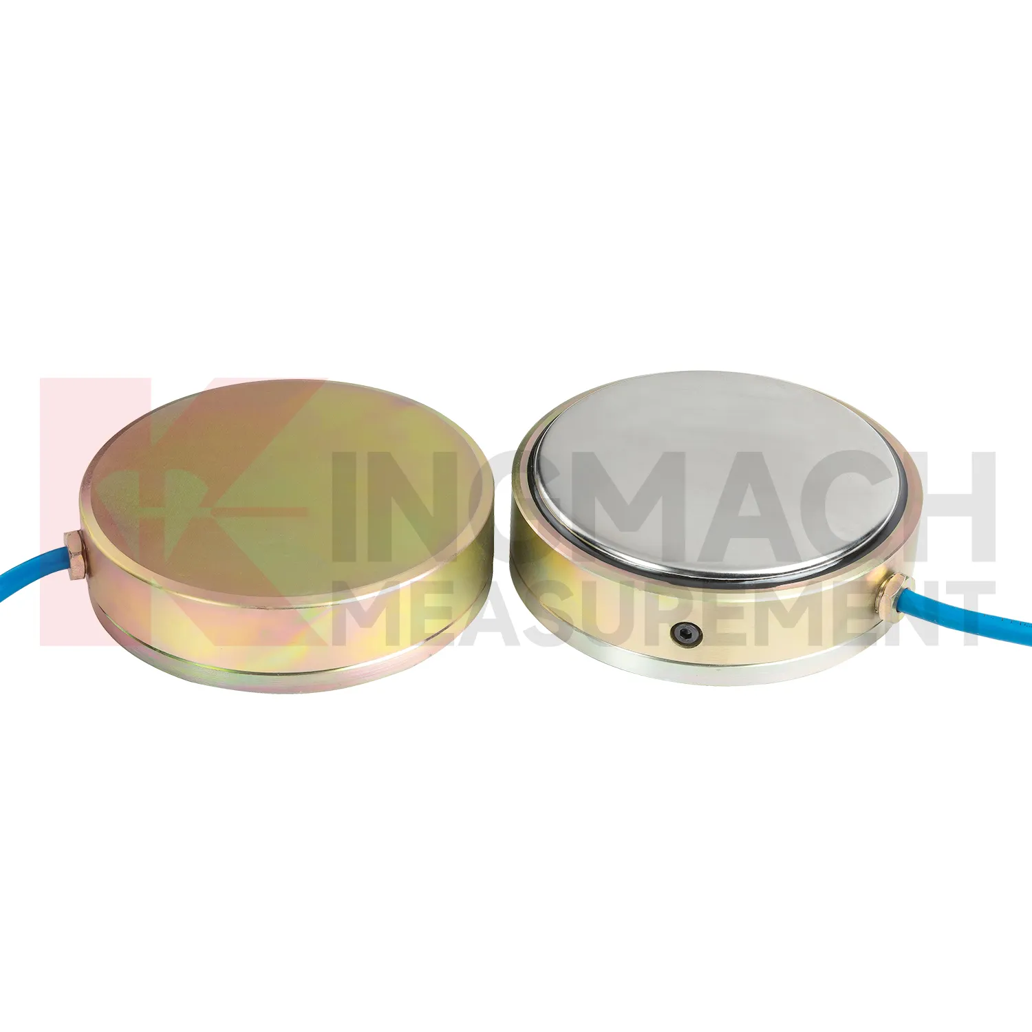
load cell wiring diagram is not limited to weighing or lab testing. In Kingmach's project world, it is part of structural and geotechnical monitoring, where the object being measured may be a cable, a pier support, a pile, a retaining wall, a tunnel support, or a dam anchor. The instrument must survive rough installation and still return a clear force or pressure value. Capacity, sensitivity, accuracy, overload allowance, waterproofing, and temperature behavior all affect whether the data can be trusted months later. A sensor with the wrong range may flatten important changes or overload during construction. A sensor with poor protection may drift after water enters a connector. A sensor with unclear calibration records may create doubt during acceptance. The better approach is to match the instrument to the loading path and the reading method at the same time. That keeps procurement, installation, and data review working from the same assumptions. Those details keep the instrument useful after the original installation crew has left the site.
FAQ
Q: Can load cell wiring diagram be used for soil pressure or retaining wall pressure? A: Yes, pressure related models such as earth pressure cells are used where the measured value is contact pressure rather than direct member force. Q: What ranges are listed for Kingmach earth pressure cells? A: The JMZX-50XXAT/ATM family lists 0.3 MPa, 0.6 MPa, 1 MPa, 2 MPa, 4 MPa, 6 MPa, and 8 MPa ranges. Q: What accuracy and resolution are listed? A: The product file gives 0.001 MPa pressure resolution, 0.5%FS pressure accuracy, and ±0.5°C temperature accuracy. Q: Where are these readings useful? A: Foundation pits, dams, slopes, retaining walls, embankments, tunnels, and buried structures. Q: What maintenance issue is most common? A: Cable damage, water entry, channel confusion, and poor installation records cause many field doubts.
Reviews
David Wilson
We purchased displacement transducers and settlement sensors, and the quality exceeded our expectations. Easy installation and reliable performance.
Christopher Martinez
Very satisfied with the readouts & data loggers. User-friendly interface and supports multiple sensor inputs.
Latest Inquiries
To protect the privacy of our buyers, only public service email domains like Gmail, Yahoo, and MSN will be displayed. Additionally, only a limited portion of the inquiry content will be shown.
Charlotte***@gmail.comUnited Arab Emirates
Hi, we require instrumentation cables suitable for harsh environments. Could you advise on specifica...
Emma***@gmail.comCanada
Dear Sir/Madam, we are interested in displacement transducers and settlement sensors for a geotechni...